
Different approaches in creating a custom blendshape deformer in Maya API, Bifrost, Blender and Houdini using VEX, Python and C++
Understanding BlendShapes
Blendshape nodes are among the most important deformers used in Maya (and not just there! Similar nodes are implemented in almost every 3D software).
Different types of behaviors can be implemented, usually, the most common approach is the vertex order-based one, but UVs can be used as well.
In this post, I will go for the vertex order-based one.
Software agnostic blendShape math
The formula to get the final position of each point is rather simple, let's take a look at fig.1.
Given two geometries (SOURCE MESH, TARGET MESH), we can identify m1 and m2 as the respective transform matrices, and pos1 and pos2 as the respective positions.
To calculate the distance from the source and destination points, first of all, we will need to put them in the same space, this can mean that the target mesh can go to the source space (m2 to m1), source mesh can go to target space (m1 to m2) or they can both go to a third space (like world space for instance, in this case m3). fig.2.
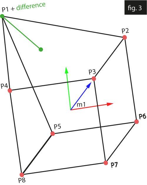
Finally, we can simply subtract pos1 from pos2 for each point, this will be the increment needed to blend from the source to the target position. The source geometry is then brought back to its original space. fig.3.


Houdini
Creating a blendShape behavior in Houdini is extremely easy with wrangle nodes. The Point wrangle node is iterating through each point in the mesh, so we don't need to implement any kind of complex setup.
Given two geometries with the same topology, and a point wrangle node with the source object plugged at pos 0 and the destination object plugged at position 1, the following VEX code will blend between the two positions:
The @paintedWeight attribute is optional and is added using an attribute paint node if you want to make the deformer paintable.
Notice that we could also use this kind of approach:
v@P = lerp(@P, v@targetP, (@blendWeight*@paintedweight)); // that linearly interpolates the two positions

Bifrost
Implementing the setup in Bifrost is simple. As Houdini does with the wrangle node, Bifrost does all the geometry iteration for us. We will just have to reuse the same equation:
newP = baseP + (targetP - baseP)*blendWeight

Blender
The approach I used in Blender, using geometry nodes, is probably the easiest one. More vector math-based ways could be used as well, but this already gives us a pretty decent result. Also, unlike the Houdini solution, this one does take into account the transforms of the geometries. I won't cover here how to implement a setup that takes into account the transforms in these cases where it is not automatically done (eg. Maya MPxDeformerNode deform method already does this for us, and also has an MMatrix& argument that represents the geometry's world space transformation matrix) as it is a bit more tricky and would require some research.
Just to give a quick tip, the main logic that I would implement to achieve that is to use matrix multiplication to have the same space for both the geometries and then use the inverse matrix to send it back after the deformation calculation.
Notice that I used mixRGB to blend between the two positions. At the end of the day, vectors3 are just arrays of 3 floats, so color nodes will usually be able to handle vectors in most cases.

Advanced: Maya API - Python prototype
To create a custom deformer node, we are going to create a child of the class Maya.OpenMayaMPx.MPxDeformerNode. Please consider that Maya python API 2.0 is not suitable to create deformers.
I will prototype the node in python and then will convert it to C++.
As this is a custom python plugin, it will need to be loaded as a plugin. Let's implement the base class and the initializePlugin and uninitializePlugin methods (these are built-in functions that Maya calls when we try to load/unload a plugin).
creator and initialize are two methods that are needed to register a new node and to create the desired attributes on that. Let's now fill the initialize method
At this point, we can start implementing the deform method, which is the one called to deform the mesh. It has four arguments, an MDataBlock&, which is used to query the values of the attributes from the node, a MItGeometry& that loops around each point of the mesh, an MMatrix& which is the world space matrix of the geometry, and an integer which is the index of the geometry plugged in the inputs of the node. Refer to the documentation to know more about that.
First of all, we will need to query a few argument values from the data block, also, I will create an MPointArray which contains all the points of the target mesh.
At this point, we are ready to iterate through the points of the base mesh and to implement the deformation,
Finally, I added a few lines to make the deformation paintable, here is the final code.
At this point, you will just have to save it as a .py file and load it as a plugin, then select the source geo, run the `deformer -type "BsDeformer"` line in the mel tab, and plug the outMesh of the target geo into the blendMesh plug.
Advanced: Maya API - C++
The conversion to c++ is pretty straightforward but requires a bit more Maya API knowledge as soon as some foundations on how to compile Maya plugins.
I won't go very in-depth since it is a pretty advanced topic, but I leave here the code, I tried to comment it as much as I could.
I usually add 3 files: An header file where I define the node class, a cpp file where I describe the overwritten methods, and a pluginMain.cpp file where I add the initializePlugin and uninitializePlugin functions.
Here is the header:
Here is the customBlendShapeDeformer.cpp
Finally, here is the pluginMain.cpp:

